 Inference
 Marketplace


Introduction
This use case demonstrates how to segment traffic on a node using VLAN sub-interfaces on physical ports and Local virtual networks. VLAN sub-interfaces let you separate management traffic from application traffic, or isolate different application workloads from each other, on the same physical port. For background on VLAN support and virtual network types, see Virtual Networks Overview.Prerequisites
- EVE-OS (Edge Virtualization Engine) 14.5.0-LTS or later on the target node.
- You have the SysManager or SysAdmin role in your enterprise. See Manage Roles.
- A node with at least three physical Ethernet ports onboarded to Edge Infrastructure Services.
- Three Local virtual networks and one Switch virtual network created on the node. See Create a Virtual Network.
- Four edge applications ready to deploy.
- An upstream switch configured with trunk ports to carry traffic for multiple VLANs.
Example Scenario
The node has three physical Ethernet ports: eth0, eth2, and eth3. The traffic is segmented as follows:- eth0 carries management traffic on VLAN 10 and application traffic for Application 1 on VLAN 20. The port is configured as VLANs Only, so untagged traffic on eth0 is dropped.
- eth2 carries application traffic for Application 2 on VLAN 30 and untagged traffic for Application 3.
- eth3 connects to a Switch virtual network. Application 4 uses an access VLAN (VLAN 100) on the Switch virtual network.
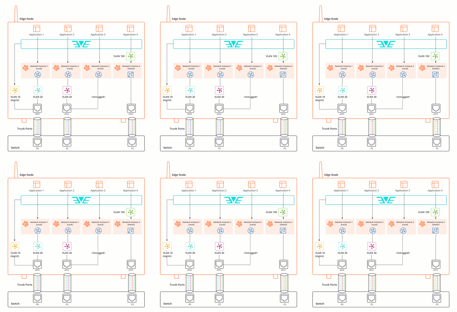
Step 1: Configure Node Adapter VLANs
Configure the VLAN sub-interfaces on the node adapters.- Open Infrastructure > Fleet > Nodes and select the target node.
- Select Configure node in the page header to open the configuration overlay.
- In the configuration overlay, open the Adapters section.
Configure eth0
eth0 is used exclusively for VLAN-tagged traffic. Untagged traffic on this port is dropped.- Set Interface Usage to VLANs Only.
- Expand the adapter options and click VLAN Details.
- Add the first VLAN sub-interface: set Logical Label to
eth0.10, VLAN ID to10, and Interface Usage to Management (this sub-interface carries EVE-OS management traffic). - Click Add Another VLAN and add the second sub-interface: set Logical Label to
eth0.20, VLAN ID to20, and Interface Usage to App Shared (this sub-interface carries Application 1 traffic). - Click Save.
Configure eth2
eth2 carries both VLAN-tagged traffic for Application 2 and untagged traffic for Application 3.- Set Interface Usage to App Shared (the port handles both tagged and untagged traffic).
- Expand the adapter options and click VLAN Details.
- Add a VLAN sub-interface: set Logical Label to
eth2.30, VLAN ID to30, and Interface Usage to App Shared. - Click Save Changes.
Configure eth3
eth3 connects to the Switch virtual network. The access VLAN for Application 4 is configured during application deployment, not at the adapter level.- Set Interface Usage to App Shared.
- Click Save.
Step 2: Assign Virtual Network Ports
Assign the correct VLAN sub-interface to each Local virtual network.- In the sidebar, click Infrastructure > Workloads > Virtual Networks.
- Click the Local virtual network you want to use for Application 1 traffic.
- Click the Configure button (gear icon).
- In the Interface sub-tab, set the Port to eth0.20 (VLAN 20).
- Click Save Changes.
- Click the Local virtual network you want to use for Application 2 traffic.
- Click the Configure button.
- In the Interface sub-tab, set the Port to eth2.30 (VLAN 30).
- Click Save Changes.
- Click the Local virtual network you want to use for Application 3 traffic.
- Click the Configure button.
- In the Interface sub-tab, set the Port to eth2 (the parent interface, for untagged traffic).
- Click Save Changes.
Step 3: Deploy Application 4 with an Access VLAN
The access VLAN for Application 4 is configured on the network adapter during application deployment, not on the Switch virtual network itself.- Deploy Application 4 using Deploy an Application Instance.
- In the Adapters and Networks section, select the Switch virtual network for the adapter on eth3, expand the adapter options, and enter
100in the Access VLAN ID field. - Complete the deployment.
Result
After completing this configuration:- EVE-OS management traffic runs on the dedicated VLAN 10 sub-interface of eth0, isolated from application traffic.
- Application 1 traffic uses VLAN 20 on eth0, isolated from the management VLAN.
- Application 2 traffic uses VLAN 30 on eth2, isolated from untagged Application 3 traffic that also uses eth2.
- Application 4 connects to the Switch virtual network on eth3 with VLAN 100 access port isolation.
Next Steps
Virtual Networks Overview
Reference documentation on VLANs, adapter configuration, and virtual network types.
L2 Switching with Access VLANs
A related use case using Switch virtual networks with access VLANs.
L2 Switching and Management VLAN on a Single Interface
A use case that combines access VLANs and management VLAN sub-interfaces on a single port (available in EVE-OS 14.5.2-LTS and later).
Create a Virtual Network
The full virtual network creation walkthrough.