 Inference
 Marketplace


Introduction
Virtual networks provide network connectivity for edge application instances running on the same node. Each application instance connects to one or more virtual networks through virtual network interfaces, controlling how it communicates with other applications on the node, with external networks, and with devices on the physical network. Virtual Networks were previously called Network Instances. In Edge Infrastructure Services, virtual networks are created and managed under Infrastructure > Workloads > Virtual Networks in the new UI. You can create two types of virtual networks: Local and Switch.Prerequisites
- You have the SysManager or SysAdmin role in your enterprise. See Manage Roles.
- A node onboarded to Edge Infrastructure Services.
- Familiarity with networking concepts including IP addressing, subnets, gateways, and DNS.
How It Works
When you create a virtual network, you assign it to a node (or cluster) and configure the type and network settings. Edge Infrastructure Services provisions the virtual network on the target node through EVE-OS (Edge Virtualization Engine). Application instances can then attach to the virtual network during deployment or at any time afterward. EVE-OS manages the virtual network on the node, enforcing isolation between virtual networks, running a built-in DHCP server for Local networks, and forwarding or bridging traffic according to the network type.Virtual Network Types
Local virtual network
A Local virtual network creates an isolated virtual subnet on the node. Applications attached to the network receive IP addresses from EVE-OS through DHCP or static assignment. Traffic between the applications and external networks is routed through the configured physical port on the node. You configure IP settings when creating a Local virtual network, including subnet, gateway, DNS server, NTP server, IP address range, and optional static routes. Local virtual networks support multi-path routing with failover, making them suitable for deployments that require redundant network connectivity.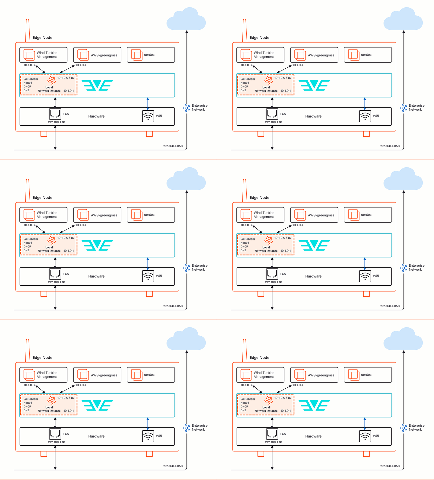
Switch virtual network
A Switch virtual network creates a Layer 2 bridge between application instances and a physical network port on the node. Applications attached to a Switch virtual network appear as separate devices on the physical network and can obtain IP addresses directly from the network’s DHCP server, just as a physical machine would. Switch virtual networks are useful when applications need to share the same IP subnet as devices on another network, or when the application must be directly accessible from the physical network without NAT. Switch virtual networks do not include IP configuration settings. Applications handle their own IP addressing.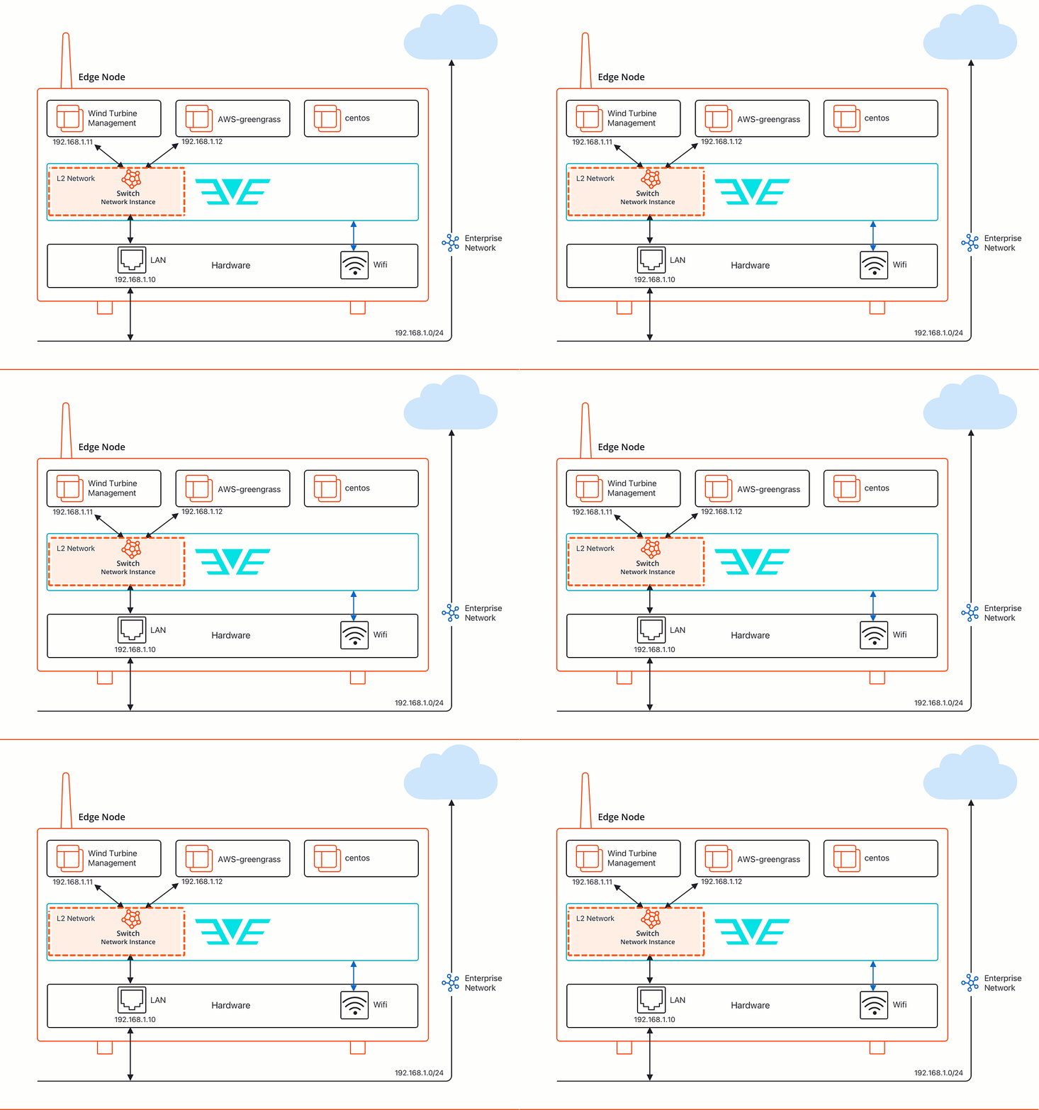
Ports and Adapters
When creating a virtual network, you assign it to a physical port on the node. The available port options depend on how the node was configured at onboarding. Options include individual physical ports, VLAN sub-interfaces, Link Aggregation Groups (LAGs), and adapter labels.Adapter labels
Adapter labels group multiple physical ports under a single label. Selecting an adapter label as the virtual network port lets you create a multi-path virtual network that uses multiple ports simultaneously. EVE-OS probes all ports in the group and automatically routes traffic through the port with the best connectivity, providing failover across ports.VLANs
VLANs segment a single physical port into multiple logical networks. EVE-OS supports VLAN sub-interfaces on Local virtual networks and access VLANs on Switch virtual networks. Starting with EVE-OS 14.5.2-LTS, you can combine VLAN sub-interfaces and Switch virtual network access VLANs on the same physical port.Link aggregation groups
A Link Aggregation Group (LAG) combines two or more physical ports into a single logical adapter, distributing traffic across member ports according to a configured bond mode. LAGs increase bandwidth, provide redundancy, and improve resilience for deployments that require high availability.IP Configuration Options
DHCP and static IP assignment
Local virtual networks support both DHCP (automatic) and Static IP assignment. When using DHCP, EVE-OS assigns IP addresses dynamically to application instances from the configured address range. When using Static, you specify fixed IP addresses for each application instance.Maximum transmission unit (MTU)
The MTU defines the largest IP packet the virtual network can carry. Smaller MTU values help avoid packet fragmentation when packet encapsulation is in use. Larger MTU values reduce overhead and improve throughput. If you do not specify an MTU, EVE-OS uses 1500 bytes for air-gapped networks or the lowest MTU among the associated physical ports for networks with external connectivity.Static routes
Static routes direct specific traffic to a configured gateway or output port. They are typically used when application traffic needs to reach external networks that are more than one routing hop away. You can assign an adapter label as the output port to create a multi-path static route with automatic failover.Connected routes
Connected routes propagate routing information about the physical port’s subnet directly to application instances through DHCP. They allow application traffic destined to directly connected subnets to be routed correctly without requiring manual static route configuration.Probing
Probing monitors the reachability of routes when multiple output ports are available through an adapter label. EVE-OS checks each port’s connectivity every 15 seconds using ICMP ping and runs a configurable custom probe every 2.5 minutes. When a port loses connectivity, EVE-OS automatically switches traffic to a working port.Key Benefits
- Application instances on the same node can communicate over isolated virtual networks without exposing traffic to the physical network.
- Local virtual networks support multi-path routing and automatic failover, improving application availability when the node has multiple network interfaces.
- Switch virtual networks allow applications to participate directly in the physical network, enabling DHCP-based IP assignment and direct network access without NAT.
- VLAN support lets a single physical port carry traffic for multiple virtual networks, reducing hardware requirements for nodes with limited ports.
- Adapter labels and Link Aggregation Groups provide flexible port grouping for redundancy and load distribution.
Next Steps
Create a Virtual Network
Create a Local or Switch virtual network on a node.
Manage a Virtual Network
View details, update configuration, and delete virtual networks.
Multi-Path Routing and Failover
A use case that demonstrates adapter labels and probing with a Local virtual network.
L2 Switching with Access VLANs
A use case that demonstrates Switch virtual networks with VLAN isolation.